Simulating the German Enigma Cipher Machine
 click pic
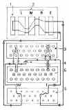
Figure 1: Details of an Enigma rotor:
(1) The finger notches used to turn
the rotors to a start position.
(2) The alphabet RING or tyre round the circumference of the rotor
(3) The shaft upon which the rotors turn.
(4) The catch which locks the alphabet ring to the core (5).
(5) The CORE containing the cross-wiring between contacts (6) and discs
(7). It is the core which effects the essential alphabetic substitution.
(6) The spring loaded contacts to make contact with the next rotor.
(7) The discs embedded into the core to make contact with the
spring-loaded contacts in the next rotor.
(8) The CARRY notch attached to the alphabet ring (see text below for
explanation).
Circuit Diagram of the Enigma with Plugboard
 click pic
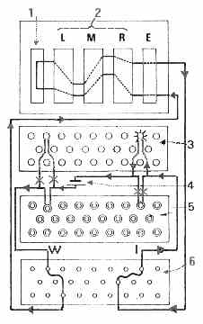
The keyboard was laid out as follows:
Q W E R T Z U
I O
A S D F G H J K
P Y X C V B N M L
The same arrangement was used
for the lamp panel and the plugboard.
The current then flows through the internal wiring in the rotors (2) to the reflector (1). Here it is turned round and flows back through the rotors in the reverse direction emerging from the entry disc at terminal H. Terminal H on the Entry disc is connected to socket H on the plug board (6) but this socket is plugged to socket I so finally the current flows to lamp I which lights up.
Thus in this instance, the letter W is enciphered to I.
A recurring request here is people asking for the enigma wheel wiring so that they can write their own simulator. To save
repetition, this web page contains the information you will need if you want to build yourself a simulator.
Wheel Wiring for 1-5:-
m_rotor[0].loadWiring("EKMFLGDQVZNTOWYHXUSPAIBRCJ");
m_rotor[1].loadWiring("AJDKSIRUXBLHWTMCQGZNPYFVOE");
m_rotor[2].loadWiring("BDFHJLCPRTXVZNYEIWGAKMUSQO");
m_rotor[3].loadWiring("ESOVPZJAYQUIRHXLNFTGKDCMWB");
m_rotor[4].loadWiring("VZBRGITYUPSDNHLXAWMJQOFECK");
for 6-8 of the naval enigma:-
m_rotor[5].loadWiring("JPGVOUMFYQBENHZRDKASXLICTW");
m_rotor[6].loadWiring("NZJHGRCXMYSWBOUFAIVLPEKQDT");
m_rotor[7].loadWiring("FKQHTLXOCBJSPDZRAMEWNIUYGV");
The reflectors were wired as follows:
'B' reflector:-
m_reflectors[0].loadWiring("YRUHQSLDPXNGOKMIEBFZCWVJAT");
'C' reflector:-
m_reflectors[1].loadWiring("FVPJIAOYEDRZXWGCTKUQSBNMHL");
The 4 rotor naval enigma could only use one of two 'thin' rotors Beta
and Gamma in the leftmost position:-
m_betaRotor.loadWiring("LEYJVCNIXWPBQMDRTAKZGFUHOS");
m_gammaRotor.loadWiring("FSOKANUERHMBTIYCWLQPZXVGJD");
It also had different reflectors:
'B' reflector:-
m_reflectors[2].loadWiring("ENKQAUYWJICOPBLMDXZVFTHRGS");
'C' reflector:-
m_reflectors[3].loadWiring("RDOBJNTKVEHMLFCWZAXGYIPSUQ");
The reason is so that the British could decode 3 rotor traffic as the combination
of (I think) beta and 'B' is the same as the 3 rotor 'B' reflector and the same for 'C' and gamma.
The special 'thin' rotors and reflector in the 4 rotor machine fitted into the same space occupied by the reflector of the 3 rotor machine. There was no
drive to the fourth rotor, so it only could only be moved manually during the
setup of the machine. The keyboard to entry wheel wiring is in straight A-Z order on
the military enigmas.
Carry Positions
You also need to know the notch positions - these control where the rotors 'carry' to movement their neighbors:-
m_rotor[0].notch('Q');
m_rotor[1].notch('E');
m_rotor[2].notch('V');
m_rotor[3].notch('J');
m_rotor[4].notch('Z');
m_rotor[5].notch('Z','M');
m_rotor[6].notch('Z','M');
m_rotor[7].notch('Z','M');
Wheel Turnover and The Anomaly
Most people assume that the rotors are driven in a manner similar to a car odometer.
This is not the case, although the behavior is similar enough to make you think so. There is however a crucial difference which if you don't understand,
will result in your simulator being incorrect.
First the basics of the rotor drive mechanism. The mechanism is a mechanical arrangement driven by the downward motion of the key being pressed. This leads
me to the first point of note - the rightmost rotor moves on each keystroke BEFORE the circuit completion and
enciphering is done.
To understand how the middle and left rotor move, we must look at the 'carry' mechanism. On each rotor's alphabet ring, there are 26 notches on the right
hand side. The left hand side has a single notch (for wheels 1 to 5 at least, wheels 6, 7 and 8 have two notches on this side). The carry mechanism uses a 'T' shaped pushrod between the neighboring rotors which moves back and forth with each keystroke. When the wheel to the right of the pushrod reaches its notch position, the right hand branch of the pushrod's 'T' falls into the
notch. The left hand branch can then engage one of the 26 notches in the rotor to the left. On the next keystroke, the pushrod moves BOTH rotors (again, before the keystroke is enciphered). When the wheel to the right of the pushrod is not at its notch position, the solid part of the alphabet ring prevents the pushrod from engaging
the wheel to its left.
When we look at the carry between the right and middle rotors, this mechanism produces an effect which is identical to an odometer (we'll look at why in a minute).
For the middle and left rotors, the effect is quite surprising. To see why, let's
go through an example: assume that the middle rotor is 1 position away from its notch position and the right rotor is at its notch position. When a key is pressed, the middle-to-right pushrod moves both the right and middle rotors, as we would
expect. The keystroke is then enciphered. Now the middle rotor is at its notch
position so the left-to-middle pushrod engages the middle rotor's notch and one of the 26 notches in the right hand side of the left rotor. On the next keystroke, BOTH the middle and the left rotor
move. The right rotor moves on all keystrokes, so ALL of the rotors move together. The surprising effect is that the middle rotor has moved twice on successive keystrokes, which is NOT what an odometer would lead us to
expect.
The anomaly exists between both the left-and-middle rotors and the middle-and-right rotors, but as the right rotor always moves with each keystroke, we do not observe any difference in the effect of the mechanism.
To see the anomaly in action, fit the rotors in the order 1,2,3 and set the indicators to 'EDV' (The ring settings don't matter as the turnover mechanism is on the alphabet rings, not the wheel cores). The first keystroke should move the indicator to 'EEW' and the next should move all 3 rotors, resulting in an indicator of 'FFX'.A worked example:
Then set up the enigma as follows:
Wheel Order: 123
Ring Settings: 111 (or AAA)
Indicator Settings: AAA
Steckers: None
PlainText: ABCDEFG
This gives the cyphertext BJELRQZ. Here's the trace
and an explanation:
ABDC CCDD DDFF F->S SSSS SSEE EFCB
BDHF FFII IIVV V->W WWNN NNTT TVLJ
CFLI IIXX XXRR R->B BBWW WWMM MPHE
DHPL LLHH HHQQ Q->E EEAA AAAA AEPL
EJTO OOMM MMOO O->M MMCC CCPP PUWR
FLVP PPCC CCMM M->O OOMM MMOO OUWQ
GNNG GGRR RRUU U->C CCYY YYVV VCGZ
Rotor 1: ABCDEFGHIJKLMNOPQRSTUVWXYZ
EKMFLGDQVZNTOWYHXUSPAIBRCJ
Rotor 2: ABCDEFGHIJKLMNOPQRSTUVWXYZ
AJDKSIRUXBLHWTMCQGZNPYFVOE
Rotor 3: ABCDEFGHIJKLMNOPQRSTUVWXYZ
BDFHJLCPRTXVZNYEIWGAKMUSQO
Reflector: ABCDEFGHIJKLMNOPQRSTUVWXYZ
YRUHQSLDPXNGOKMIEBFZCWVJAT
The A is unchanged by the stecker. The keystroke advances the right rotor (3) BEFORE encryption, so the A is delivered to the B terminal on rotor 3. Rotor 3 changes it to a D. This is then passed across in the C position (after adjusting for the rotor offset from its neutral position) to the middle rotor (2). Both middle (2) and left (1) rotors are in their neutral positions so we can just apply the wiring transformations
without worrying about offsets, so C becomes D and then D becomes F.
The reflector turns the F to S, then on the return path, the left rotor makes no change, the middle
changes S to E (note that we are going in the opposite direction now). We then adjust for the offset, so the E activates the F terminal on the right rotor (3), which transforms it to a C. Readjusting for the offset
gives terminal B. Passing again through the stecker gives no change.
Well Done (or at least medium rare). GO BACK
Portions From Angelshaft
maschinenwerk
patent 1921
by courtesy Copyright (c) 1999, Andy
Carlson.